Naturally limited conditions may occur such as the stability, the power of the machine and the clamping. These mean the indicated estimates cannot be used. Generally you will find that the estimates are very good startup values from where you can fine tune for an even better result. When at first glance the initial estimates seem too high for you, it is best to start off with a 20 to 40% lower startup. You will however risk reaching out of the ideal chip breaking circumstances. When you would like to start off with the optimal estimates, please contact us for additional advice.
Tips to prevent tremblances:
> decrease or increase the cutting speed
> decrease or increase the feed rate
> choose for a positive clamping holder and insert (preferably ground)
> clamp the tool as close as possible to the holder
> choose a geometry for fi ne machining
> clamp the workpiece as stable as is possible
Tips for choosing Boring Tools with corresponding inserts:
> choose for the biggest Boring Tool diameter
> choose for the shortest overhang
> when possible, cool through the Tool, which not only cools but also enables the chips to be removed quickly
> choose for the smallest nose radius
Tips for preventing a bad surface:
> lower the feed
> increase the cutting speed
> use lubrifi cation (or grease)
> choose for an easy cutting insert (ground or positive)
> améliorer la stabilité de l’outil et de la pièce.
Indications and explanation of the insert geometry:
1st position:
NF2 N = Negative Insert (reversible)
PF2 P = Positive Insert
2nd position:
NF2 F = Fijn (licht draaiwerk, nadraaien)
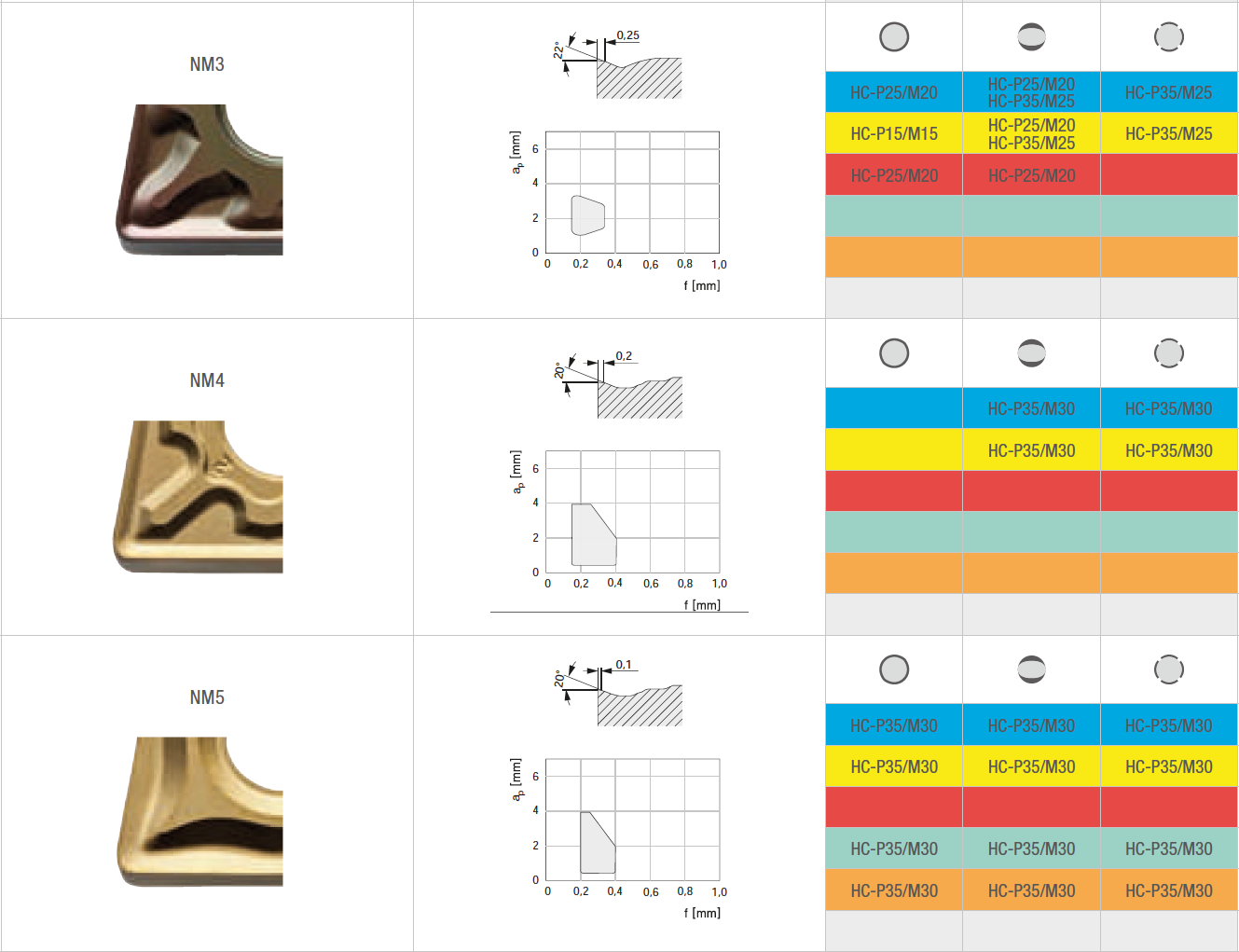
NM3 M = Medium (general usage)
NR4 R = Roughing (Roughing, interrupted cutting)
PA2 A = Aluminium (Geometry for Aluminium)
3rd position:
PF2 2 : The lower the number, the more the geometry is set for small chip sections
NR4 4 : The higher the number, the stronger the geometry is
Formulas per geometry voor the calculation of feed (f) and cutting depth (ap) are::
| NF2 | ap min | = nose radius (mm) |
| ap max | = 2,4 mm | |
| f min | = 0,15 x nose radius | |
| f max | = 0,26 x nose radius | |
| NM3 | ap min | = 1,2 x nose radius (mm) |
| ap max | = 0,35 x cutting length | |
| f min | = 0,28 x nose radius | |
| f max | = 0,55 x nose radius | |
| NR4 | ap min | = 2 x nose radius |
| ap max | = 0,4 x cutting length | |
| f min | = 0,4 x nose radius | |
| f max | = 0,65 x nose radius | |
| PM3 | ap min | = 1,25 x nose radius |
| ap max | = 0,33 x cutting length | |
| f min | = 0,25 x nose radius | |
| f max | = 0,52 x nose radius | |
| PM4 | ap min | = 1,25 x nose radius |
| ap max | = 0,33 x cutting length | |
| f min | = 0,28 x nose radius | |
| f max | = 0,52 x nose radius | |